On NetGen a 3D model can be meshed under a great variety of meshing controls in order to adjust de meshing density to the desired especifications.
Netgen is open source based on the LGPL license. It is available for Unix/Linux and Windows.
You can find it here:
Here it is a simple step by step tutorial wich can be a guide in the process of meshing with NetGen and analysing in CalculiX
Before start please consider the next author notes.
Note 1: In this case, a 3D model on ( .igs) format will be use, any other format can be use for with this process only with a few changes on the geometry repairing step.
Note 2: In this case a very complex 3D model was used to test the NetGen capabilities to maximun, the reader can (and it is advise to) choose to use a simple model first in order to understand the steps of the tutorial and then try bigger tasks.
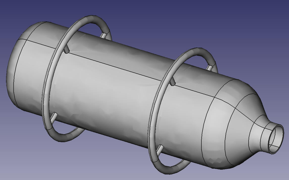
On your own 3D model make sure you have a single body geometry (at least for this tutorial) without any zero volumen regions like intersections. Also, make sure your file its exported on .igs format, the extension on lowercase.
After a while the model will appear on the working area, it is recommendable that the reader learn to differ between the colors that NetGen assign to the faces of the models, the brighter green face represent the external side of the face ( the one facing the space with no volume) and the dark ones represent the internal side ( the ones facing the volumen of the model); by this way the reader can determine when a body have any error over it’s faces alignment.
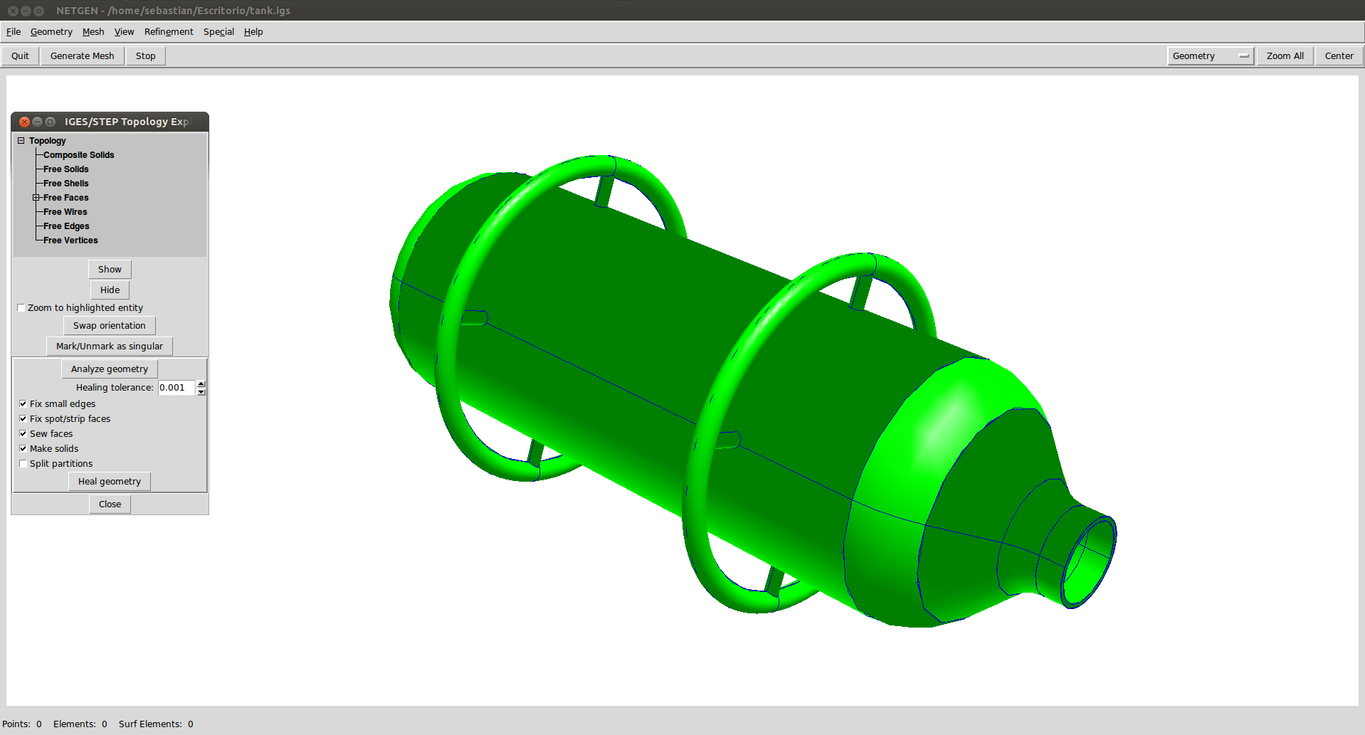
Simply click on Geometry and then IGES/STEP Topology Explorer/Doctor and select Analize Geometry and when finish Heal Geometry, this will adjust the faces of the model to fit in to the body without make any dimensional change.
The color of the faces will change to its correct order.
Even if the .igs model have no error on its faces it is recomendable to perform this healing just in case.
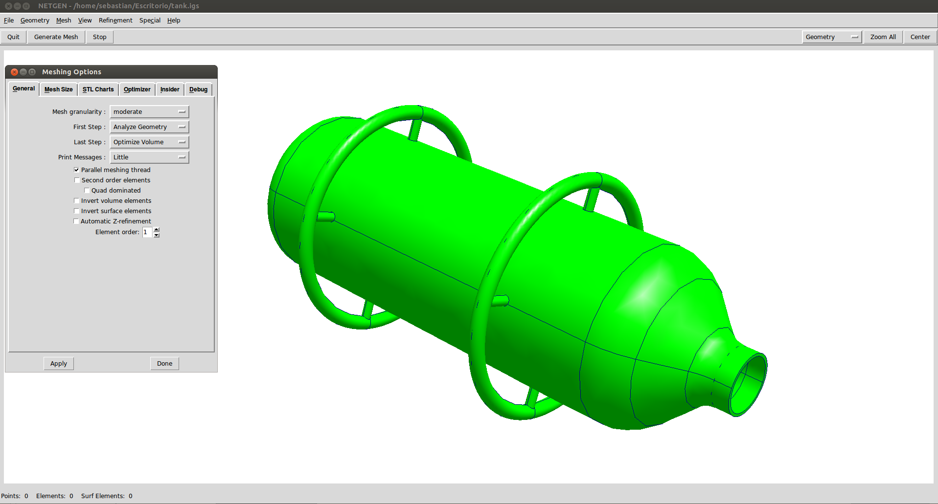
In the new windows the meshing parameters will appear, where the user
can define the steps that the program will follow to create de mesh.
Also the mesh quality can be selected from a list, in this case the
quality will be selected as Very Fine to create a nice uniform surface
around de small circular curves, click on Apply and Ok to close the
window and finaly hit Ctrl-m to start the meshig process.
The process of meshin will first create the faces meshing and finaly the
3D element columen, after your model end meshing make sure you have a
number of 3D elements and no just 2D elements.
The mesh density can be changed after the initial mesh is created so that will not be a problem.
If the reader is meshing the tutoria’s model be aware that this process can take a very, very long time depending on your machine
Anyway, the way to do it in any other mesh is clickin in the subdividing Refinement Uniform option at in Refinement menu.
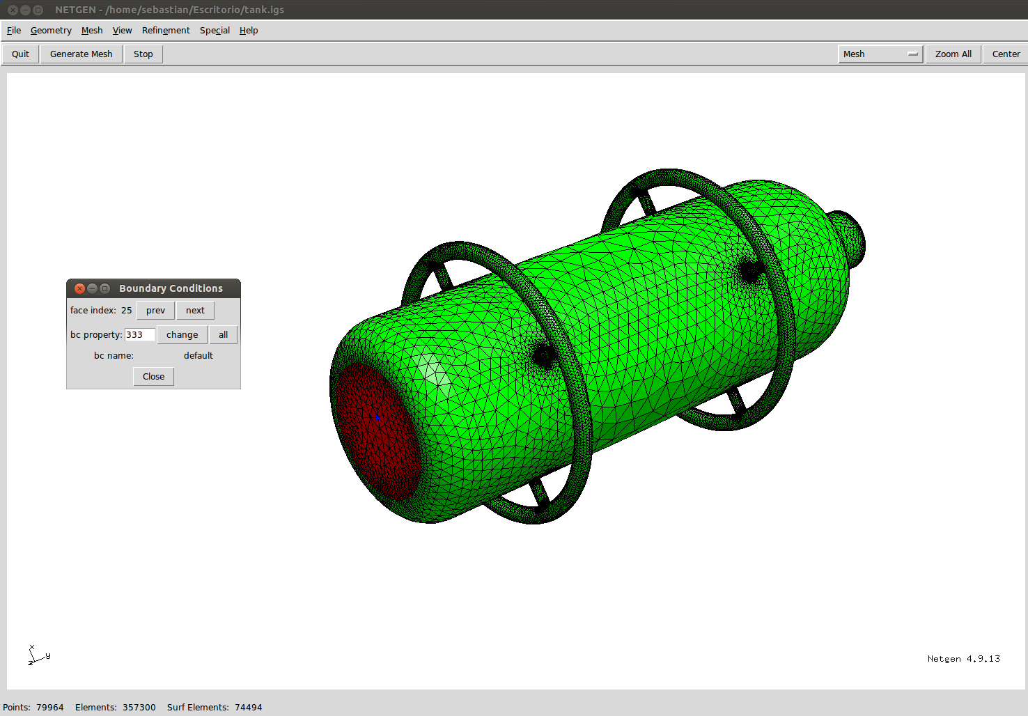
One of the greatest issues on CGX ( the pre and post processing module on CalculiX) it is the lack of a way to properly select an area or a side of the model to define some boundary conditions or to apply loads, where the proces of selecting element faces one by one on complex geometries is tremendously complicated. This issue can be solve by marking this faces with a set prevously on NetGen.
For this go to Mesh/ Edit Boundary Conditions , a little window will appear from here the name faces will be assign.
Double click the face and then write the name of the fixed face (333) and finaly Change, doing the same thing for the load face (111).
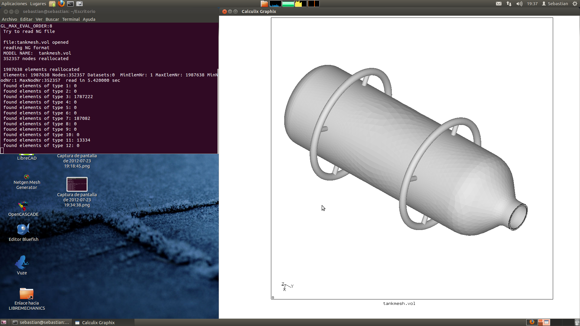
$ cgx -ng tank.vol
Change ccx for your own CalculiX command for the pre processing module CGX and tankmesh.vol for the name you have choose for your mesh. After a while, depending of the size of the mesh file, the 3D model will appear.
NetGen exports the mesh with 3D volume elements and a set of diferent 2D surface elements on all they faces, the idea is to extract the just the 3D elements from the whole file whit its own set name.
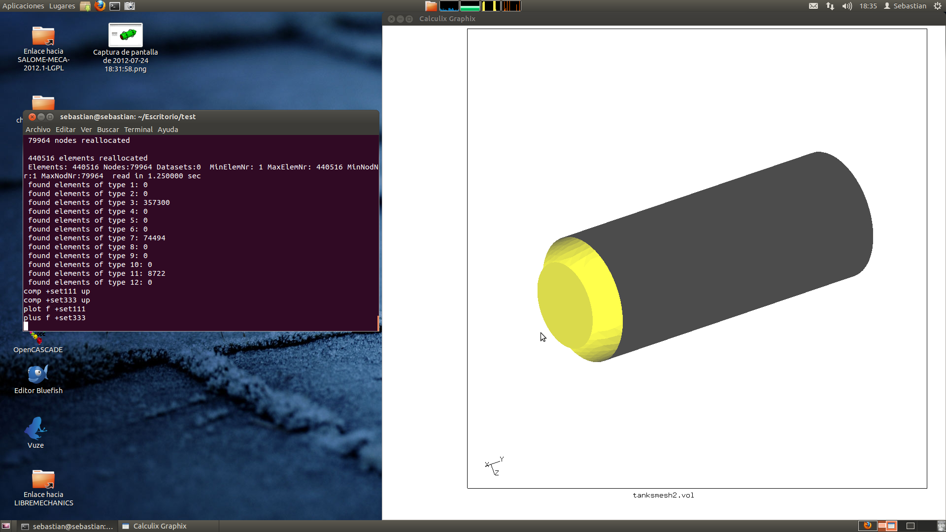
The sets created on NetGen can be listed by the command: prnt se ; the sets name start by +setxxx and in the x’s field the (111) and the (333) names created previusly will appear.
The process for translating the sets are quite easy, just follow the next process for separate the 3D elements:
- comp +setXXX up
- comp +setYYY up
- plot f +setXXX (this will show up the faces of the set XXX)
- plot f +setYYY (this will show up the faces of the set YYY)
From here you can change, add, delete and mix the faces sets for your own work, for this model the 333 set will be exported as fix.nam (send fix abq nam) and the 333 set as load.dlo (send load abq pres 100)
The next one its the .inp file commented code for the high pressure tank analysis:
*INCLUDE,INPUT=fix.nam
*BOUNDARY
Nfix,1,3
*MATERIAL,NAME=EL
*ELASTIC
210000.,.3
*DENSITY
7.8E-9
*SOLID SECTION,ELSET=Eall,MATERIAL=EL
*STEP
*STATIC
*DLOAD
*INCLUDE, INPUT=load.dlo
*NODE FILE,NSET=Nall
U
*EL FILE,ELSET=Eall
S
*END STEP
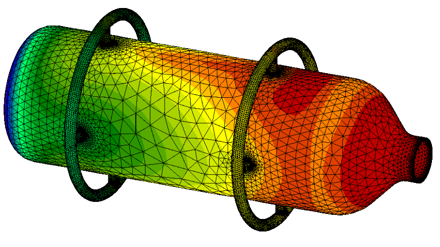
Results:
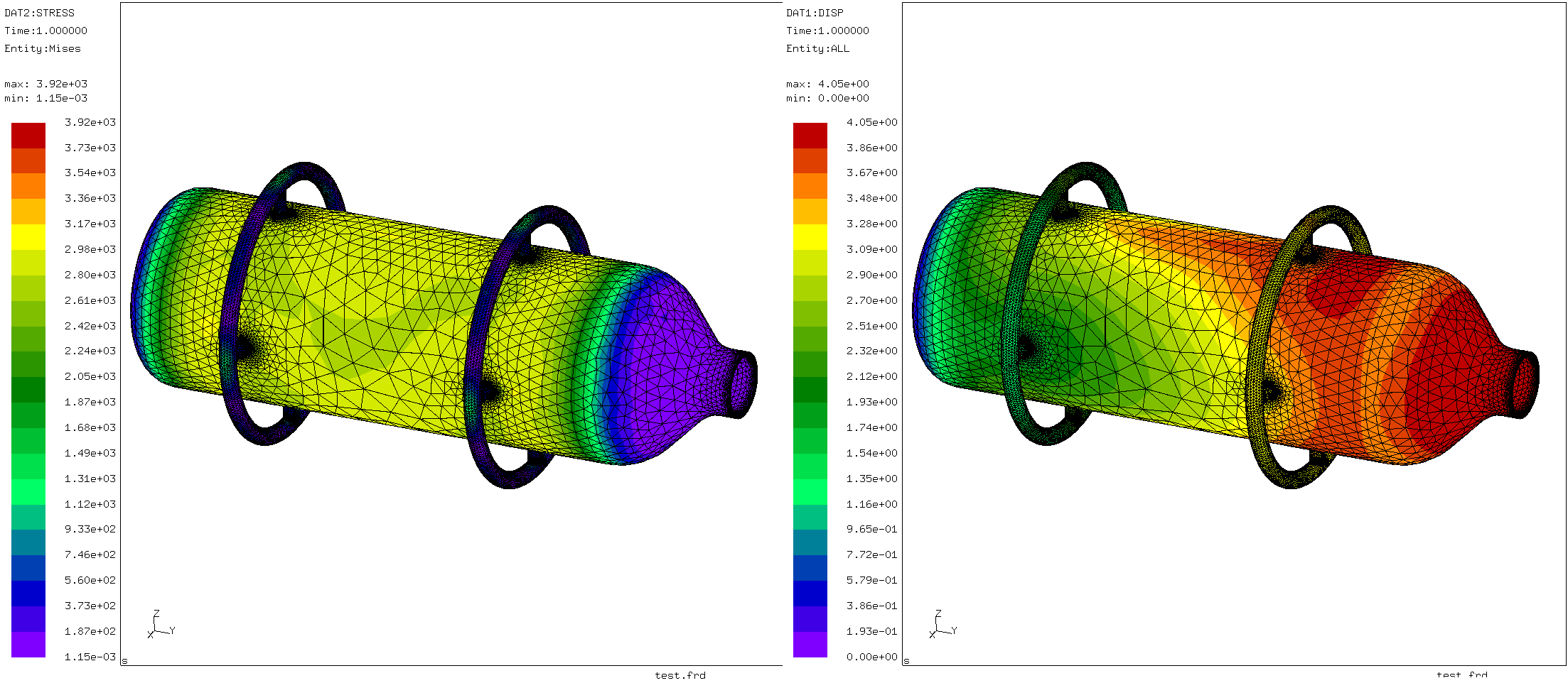
End of the tutorial.
RESOURCES:
The model, mesh, sets and .INP files can be download from SourceForge Page by this link: netgen mesh calculix analysis.zip