The programing language is really simple and can be read and understood from scratch, allowing the user to be more in contact and in control to the analisy’s structure and variables.
The program documentation its already on the web and can be get it here http://impact.sourceforge.net/Appendix_us.html , but it seems to be no effort at all to make this documentation a little more friendly to the inexperienced user or even more for ones new on the mechanical analysis’
ambit. This tutorial might be the first resource in order to get close to the program for those who want to achieve a more depply knowledge on the use and development of explicit finite element analysis.
The tutorial it’s based on a simple theory applied to a complex geometry to make a high test of the program capabilities, the new user may want to use this steps to his own simple test analisys.
More information about this great tool:
Main Source-Forge page: http://impact.sourceforge.net/index_us.html
Examples: http://impact.sourceforge.net/examples/Examples.html
Tutorial:
-
Knowing your analysis
most important thing to beginning with is to be sure of what are we are planning to do and what are we hoping to get from the process.
Usually in common implicit finite element analisys, linear elastic for example, the representation of real life cases are easily introduced to a computer-numeric field by the discretization of the model and the definition of a equilibrium matrix. On a time explicit environment, variables are quite diferents, the transformtaion of the stiffness matrix on each step of the analisys allows the material, loads, restriccions and geometry to adapt to the alterative model where the gap between each step determines the accuracy and correctness of the iteration process.
Some of the parameters should be on consider are:
- Kind of meshing
- Units
- Contacts
- Time steps
- Print steps
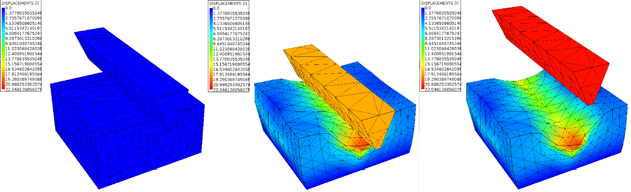
The analysis consist on a simple test of plasticity and elements discarding, an aluminium specimen it’s pierced by a steel core and then retracted to it’s original position, the ideal it’s determine the final deformed geometry of the specimen.
This is done by the constant movement restriction of the bodies and the diferences of the materials in use.
-
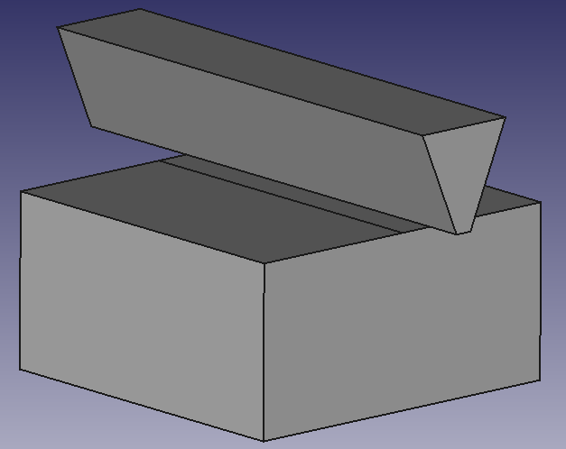
Getting the geometry.
The first step on the way to prepare the model is to get the geometry, in this case the 3D bodies of the assembly on IGES format. Actually any program can be used to build the model by just making sure to export the file on a suitable format to NETGEN, GMSH, GID or any other pre-processing program.
The 3D solids for download:
- Hard core
- Speciment body
-
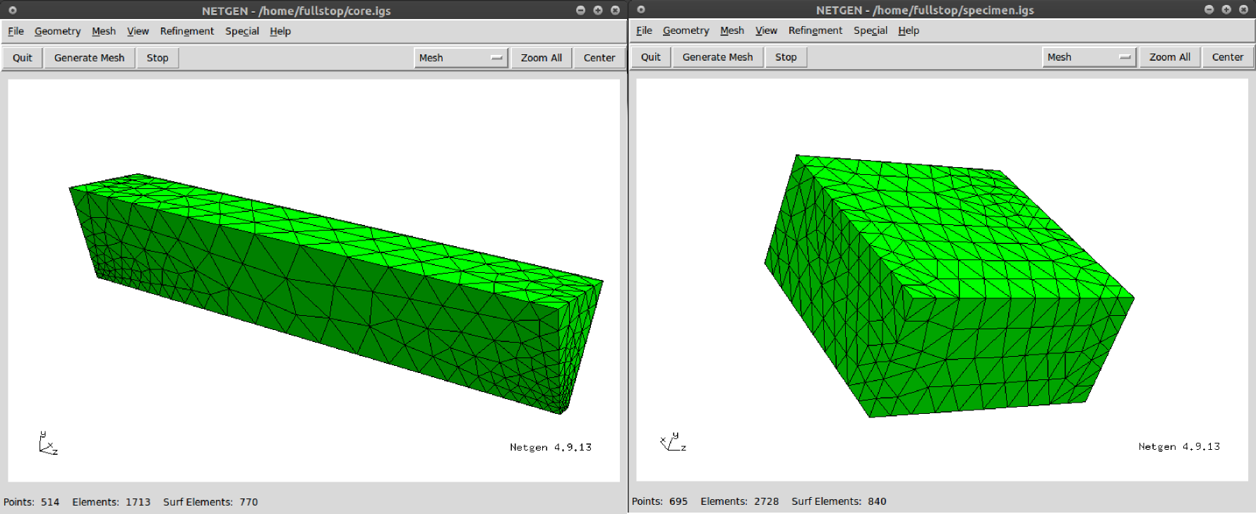
Meshing
For this tutorial the model will be meshed on NETGEN, it is also recomendable to the users to get use to work with GMSH for discretization, wich is the offcial format IMPACT reads, but by now the export method of NETGEN will do it. It is recommendable to mesh the bodies individually to have a much more precise control over the mesh
density and it’s size wich also allow to define individual properties for each body as material, restrictions and loads.
-
Importing in to IMPACT User Interface
For mesh made on NETGEN an additional step it’s required, to making sure that IMPACT can interpret the geometry, the xx.msh file most be opened first by GMSH and then saved again without any changes , just open it and save it (overwrite). Then just open de xx.msh file on IMPACT pre processing tab.
-
Setting up the analysis
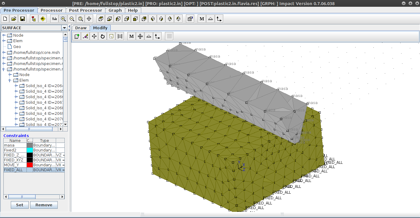
After importing the model to IMPACT and saving it as an xx.in file the properties can be modified by the graphic method or by writing on the plane-text file the lines. The xx.in file file can be found here: plastic2.in
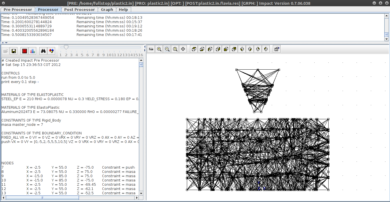
- Run Controls.
CONTROLS
run from 0.0 to 9.0 step 0.001
print every 0.1 step
- Materials.
MATERIALS OF TYPE ELASTOPLASTIC
STEEL_EP E = 210 RHO = 0.0000078 NU = 0.3 YIELD_STRESS = 0.180 EP = 0.1MATERIALS OF TYPE ElastoPlastic
Aluminum2024T3 E = 73.08075 NU = 0.330000 RHO = 0.00000277 FAILURE_STRESS = 0.4826087 YIELD_STRESS = 0.3447205 EP = 0.1
- Restrictions.
CONSTRAINTS OF TYPE Rigid_Body
masa master_node = 7
CONSTRAINTS OF TYPE BOUNDARY_CONDITION
FIXED_ALL VX = 0 VY = 0 VZ = 0 VRX = 0 VRY = 0 VRZ = 0 AX = 0 AY = 0 AZ = 0 ARX = 0 ARY = 0 ARZ = 0
push VX = 0 VY = [0,-5,1,-5,2,-5,3,-5,4,-5,5,10,6,10,7,10,8,10,9,10] VZ = 0 VRX = 0 VRY = 0 VRZ = 0 AX = 0 AY = 0 AZ = 0 ARX = 0 ARY = 0 ARZ = 0
- Contact Conditions.
ELEMENTS OF TYPE Contact_Triangle
109 nodes = [7,11,35] T = 1.0 Factor = 200.0 Friction = 0.1
110 nodes = [11,12,36] T = 1.0 Factor = 200.0 Friction = 0.1
111 nodes = [13,14,37] T = 1.0 Factor = 200.0 Friction = 0.1…
-
Solving
-
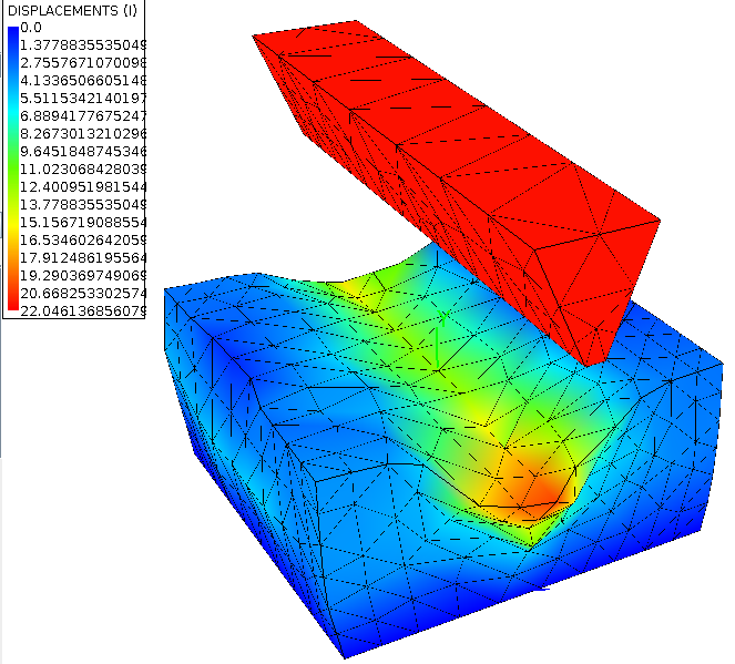
Viewing the results.
There are multiple ways to see the results from a xx.res files, the most practical one it’s by IMPACT GUI on the Post Proccesor tab, just by opening the file and waiting (long time) to load the results data.
Other much more complete ways to analyse the result file its to import the xx.res file into more specialized programs as GID. The result file can be found here plastic2.in.flavia.res