The basic operation of a stepper motor and its advantages like position control and torque holding make them a common choise on robotic and industrial aplications, however, the digital control of this kind of motors are no as simplest as regular DC machines and this instruments has not in built feedback interface. The control of this motors are given in at least two steps, the Micro Controller wich give the digital comunication and control interface and the Driver wich allow the controller to handle big power switching, commonly need it for this kind of motor.
DC brush motors rotate continuously when voltage is applied to their terminals. Stepper motors, on the other hand, effectively have multiple “toothed” electromagnets arranged around a central gear-shaped piece of iron. The electromagnets are energized by an external control circuit, such as a microcontroller. To make the motor shaft turn, first, one electromagnet is given power, which makes the gear’s teeth magnetically attracted to the electromagnet’s teeth. When the gear’s teeth are aligned to the first electromagnet, they are slightly offset from the next electromagnet. So when the next electromagnet is turned on and the first is turned off, the gear rotates slightly to align with the next one, and from there the process is repeated. Each of those rotations is called a “step”, with an integer number of steps making a full rotation. In that way, the motor can be turned by a precise angle.
The use use of multiple delay funtions on a single Arduino code means that the code has to hold the code until that conditions complay and then reasume the following code. This kind of control is the most basic and well known for controlling single speed motors, and it works pretty well, the delays set the rythm for the step shift perfectly. But when multiple motors have to be handle the use of delays over the processing code means that any step has to be preceded by the delay time of the previous motor need it to complete a step and even this way the switch for velocity means the use of diferent types of hold time.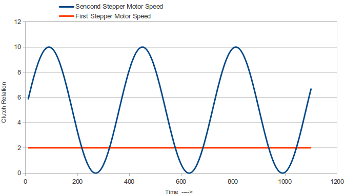
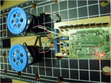
The key to succesfully control any number of steppers its to program just ONE virtual motor that gives the rythm that any other will move, like in a car, the angular speed of the wheels its a relation of the actual angular speed of the motor by the use of a CLUTH. A virtual motor moving at the top speed, that will be the reference for the other two motors, this single virtual motor has it owns regular stepper function with a single delay (actually this delay its there for the correctly serial comunication flow), the other motors work on the relation named CLUTCH wich will geve them a fraction of the virtual top speed, this is done by counting the times that the virtual motor give a step and deciding how much of them will be ignored before making a single step with it.
The CLUTH relation can be a single INT value, or a ecuation based on the time that the program has be running like int next example:
| 1 | int m11 = 2; | 39 | timer1 = 0; | 77 | digitalWrite(m24, LOW); |
| 2 | int m12 = 3; | 40 | } | 78 | dm2 = 2; |
| 3 | int m13 = 4; | 41 | } | 79 | timer2 = 0; |
| 4 | int m14 = 5; | 42 | if (timer1 == clutch1) { | 80 | } |
| 5 | int m21 = 6; | 43 | if (dm1 == 2) { | 81 | } |
| 6 | int m22 = 7; | 44 | digitalWrite(m11, LOW); | 82 | if (timer2 == clutch2) { |
| 7 | int m23 = 8; | 45 | digitalWrite(m12, HIGH); | 83 | if (dm2 == 2) { |
| 8 | int m24 = 9; | 46 | digitalWrite(m13, LOW); | 84 | digitalWrite(m21, LOW); |
| 9 | int dm1 = 1; | 47 | digitalWrite(m14, LOW); | 85 | digitalWrite(m22, HIGH); |
| 10 | int dm2 = 1; | 48 | dm1 = 3; | 86 | digitalWrite(m23, LOW); |
| 11 | int timer1 = 0; | 49 | timer1 = 0; | 87 | digitalWrite(m24, LOW); |
| 12 | int timer2 = 0; | 50 | } | 88 | dm2 = 3; |
| 13 | int clutch1 = 2; | 51 | } | 89 | timer2 = 0; |
| 14 | int clutch2 = 2; | 52 | if (timer1 == clutch1) { | 90 | } |
| 15 | int time = 0; | 53 | if (dm1 == 3) { | 91 | } |
| 16 | int a = 0; | 54 | digitalWrite(m11, LOW); | 92 | if (timer2 == clutch2) { |
| 17 | void setup() { | 55 | digitalWrite(m12, LOW); | 93 | if (dm2 == 3) { |
| 18 | pinMode(m11, OUTPUT); | 56 | digitalWrite(m13, HIGH); | 94 | digitalWrite(m21, LOW); |
| 19 | pinMode(m12, OUTPUT); | 57 | digitalWrite(m14, LOW); | 95 | digitalWrite(m22, LOW); |
| 20 | pinMode(m13, OUTPUT); | 58 | dm1 = 4; | 96 | digitalWrite(m23, HIGH); |
| 21 | pinMode(m14, OUTPUT); | 59 | timer1 = 0; | 97 | digitalWrite(m24, LOW); |
| 22 | pinMode(m21, OUTPUT); | 60 | } | 98 | dm2 = 4; |
| 23 | pinMode(m22, OUTPUT); | 61 | } | 99 | timer2 = 0; |
| 24 | pinMode(m23, OUTPUT); | 62 | if (timer1 == clutch1) { | 100 | } |
| 25 | pinMode(m24, OUTPUT); | 63 | if (dm1 == 4) { | 101 | } |
| 26 | Serial.begin(9600); | 64 | digitalWrite(m11, LOW); | 102 | if (timer2 == clutch2) { |
| 27 | } | 65 | digitalWrite(m12, LOW); | 103 | if (dm2 == 4) { |
| 28 | void loop() { | 66 | digitalWrite(m13, LOW); | 104 | digitalWrite(m21, LOW); |
| 29 | a = int((sin(radians(time/12))+1)*5)+1; | 67 | digitalWrite(m14, HIGH); | 105 | digitalWrite(m22, LOW); |
| 30 | time = time+1; | 68 | dm1 = 1; | 106 | digitalWrite(m23, LOW); |
| 31 | clutch2 = 1+a; | 69 | timer1 = 0; | 107 | digitalWrite(m24, HIGH); |
| 32 | if (timer1 == clutch1) { | 70 | } | 108 | dm2 = 1; |
| 33 | if (dm1 == 1) { | 71 | } | 109 | timer2 = 0; |
| 34 | digitalWrite(m11, HIGH); | 72 | if (timer2 == clutch2) { | 110 | } |
| 35 | digitalWrite(m12, LOW); | 73 | if (dm2 == 1) { | 111 | } |
| 36 | digitalWrite(m13, LOW); | 74 | digitalWrite(m21, HIGH); | 112 | timer1 = timer1+1; |
| 37 | digitalWrite(m14, LOW); | 75 | digitalWrite(m22, LOW); | 113 | timer2 = timer2+1; |
| 38 | dm1 = 2; | 76 | digitalWrite(m23, LOW); | 114 | delay(3); |
| 115 | } |