Some usual RF devices are those digital modules where a button or command generates an digital output on the receptor, this limits the amount of control that can be generated on the receptor to a few “channels”. In most cases some “complex” custom comunication is required, where the RF modules need to handle any type and size of information the process require.
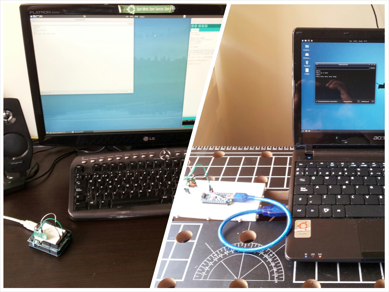
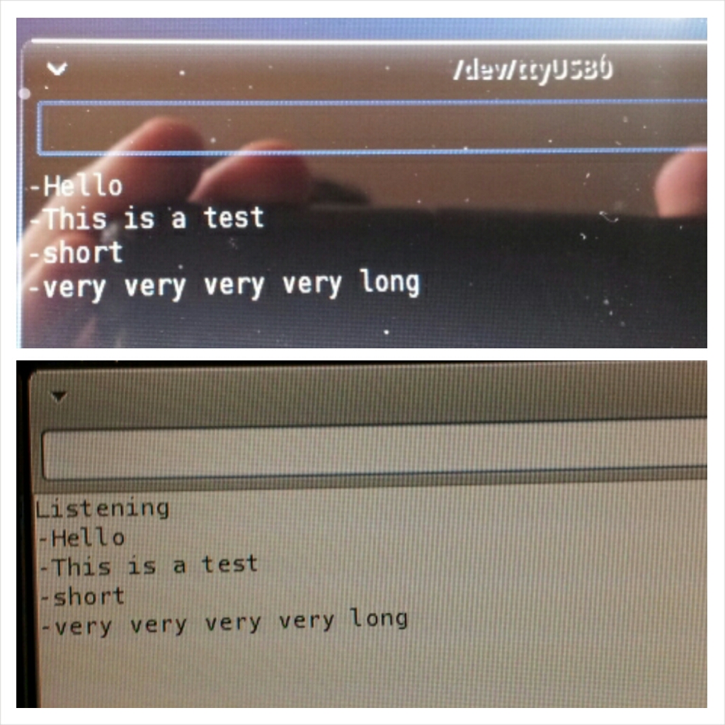
In this case an Arduino board connected to a RF transmitter that send the strings it recives via serial comunication, it send it to a receiver RF module with another Arduino board which interprets it to recreate the message on its own serial interface.
Other type of RF module, 4 channel RF controller are explained in this article: 4 Channel RD control on Arduino
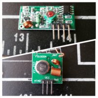
Specifications RF Transmitter Module RF 315/433 MHz
:
- Operating Voltage 3V to 12 V
- Operating Current Max ≤ 40mA (12V), Min ≤ 9mA (3V)
- Oscillator SAW (Surface Acoustic Wave) oscillator
- Frequency 315MHz~433.92MHz
- Frequency error ±150kHz(max)
- Modulation ASK/OOK
- Transfer Rate ≤10Kbps
- Transmitting power 25mW (315MHz@12V)
- Antenna Length 24cm (315MHz), 18cm (433.92MHz)
- Antenna Length 24cm (315MHz), 18cm (433.92MHz)
Some uses:
- Industrial remote control, telemetry and remote sensing.
- Alarm systems and wireless transmission for various types of low-rate digital signal.
- Remote control for various types of household appliances and electronics project.
Antena:
![]()
In this example the wire library is used to manage the data transmition to and from the RF devices:
The Wire library: This library allows you to communicate with I2C / TWI devices. On the Arduino boards with the R3 layout (1.0 pinout), the SDA (data line) and SCL (clock line) are on the pin headers close to the AREF pin. The Arduino Due has two I2C / TWI interfaces SDA1 and SCL1 are near to the AREF pin and the additional one is on pins 20 and 21. As of Arduino 1.0, the library inherits from the Stream functions, making it consistent with other read/write libraries. Because of this, send() and receive() have been replaced with read() and write().
The sprintf() function: formats and stores a series of characters and values in the array buffer. Any argument-list is converted and put out according to the corresponding format specification in the format-string. The format-string consists of ordinary characters and has the same form and function as the format-string argument for the printf() function.
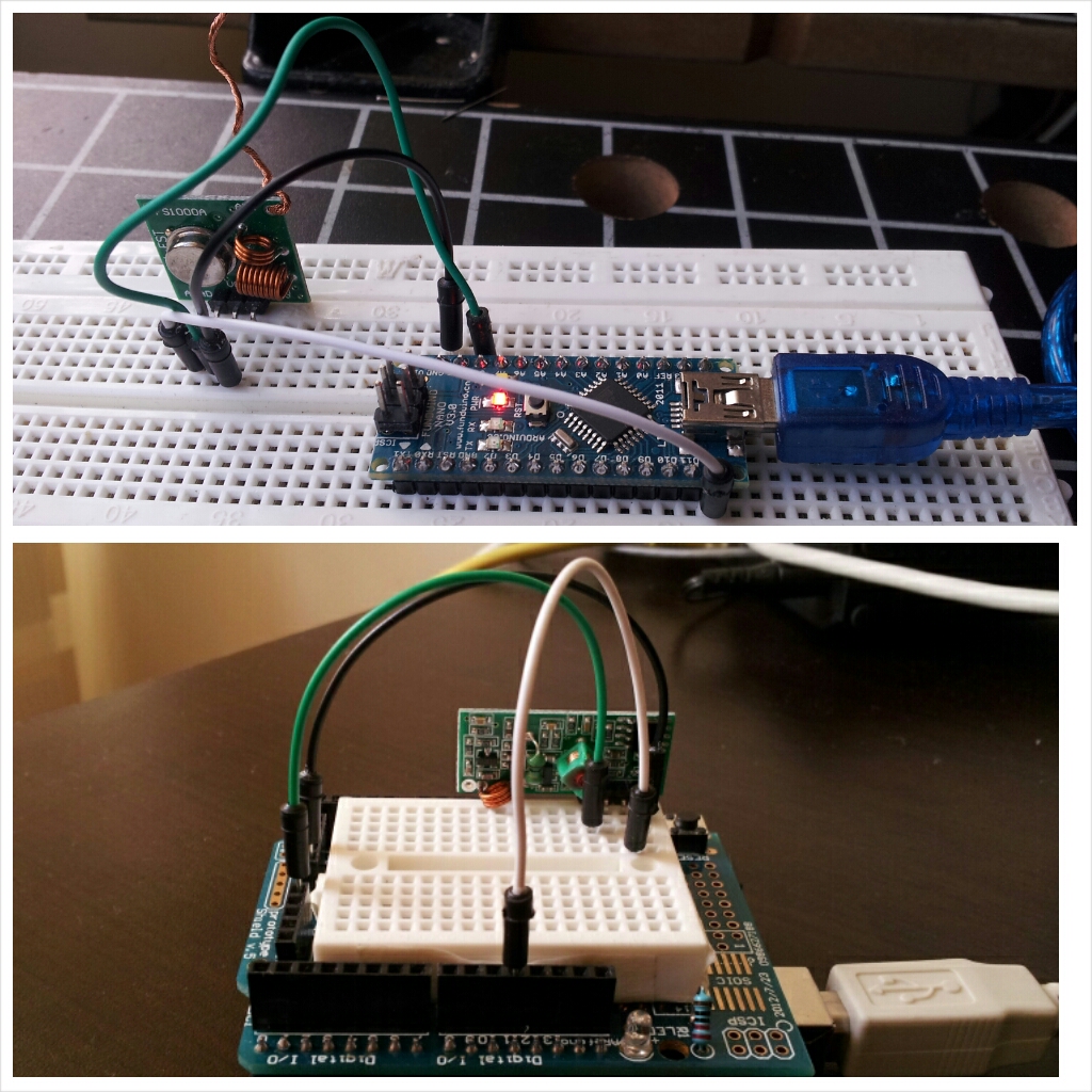
- Transmitter: VCC and GND connections are straightforward, the DATA or “ATAD” pin goes to the number 12 digital slot on the Arduino Board.
- Receive: VCC and GND connections are straightforward, one of the DATA pins goes to the number 11 digital slot on the Arduino Board.
#include <VirtualWire.h> char inData[50]; int newmessage = 0; void setup() { vw_setup(2000); vw_set_tx_pin(12); Serial.begin(9600); } void loop() { char inChar; byte index = 0; char mss[20]; while(Serial.available() > 1){ if(index < 49) { delay(10); inChar = Serial.read(); inData[index] = inChar; index++; inData[index] = ‘\0’; } newmessage = 1; } if(newmessage == 1){ inData[0] = ‘-‘; sprintf(mss, “%s”, inData); vw_send((uint8_t *)mss, strlen(mss)); vw_wait_tx(); Serial.println(mss); delay(600); newmessage = 0; // Indicate that there is no new message to wait for the new one } }
Note about the data string handling:
This measures are there to ensure that just the correct input data is transmited, as any Arduino user may know, every time a string its sent through the Arduino IDE Serial Monitor the board reads every character as an individual event including the final Return character that always follows the message. Since the return character doesnt need to be dispatched as an individual stream its rejected by the measure of the buffer in the Serial.aviable() event.
Is probable that any other method of serial communication doesn’t need this measures to clean the data chain. Its recomended to the user to first define the form of the information generated by any program, sensor or internal function to determine the way to arrange the char array.
Receiver Arduino Code:
#include <VirtualWire.h>
void setup()
{
Serial.begin(9600);
Serial.println(“Listening”);
vw_setup(2000);
vw_rx_start();
}
void loop()
{
byte message[VW_MAX_MESSAGE_LEN];
byte messageLength = VW_MAX_MESSAGE_LEN;
if (vw_get_message(message, &messageLength))
{
for (int i = 0; i < messageLength; i++)
{
Serial.write(message[i]);
}
Serial.println();
}
}
Sources:
- http://www.cytron.com.my/datasheet/WirelessDevice/RF_TX_User’s_Manual.pdf