RF modules offer the capability to wirless transmite datta on electronic and robotics projects, this modules are extremly easy to use and are quite cheap (about $5 USD) wich make them ideal for projects
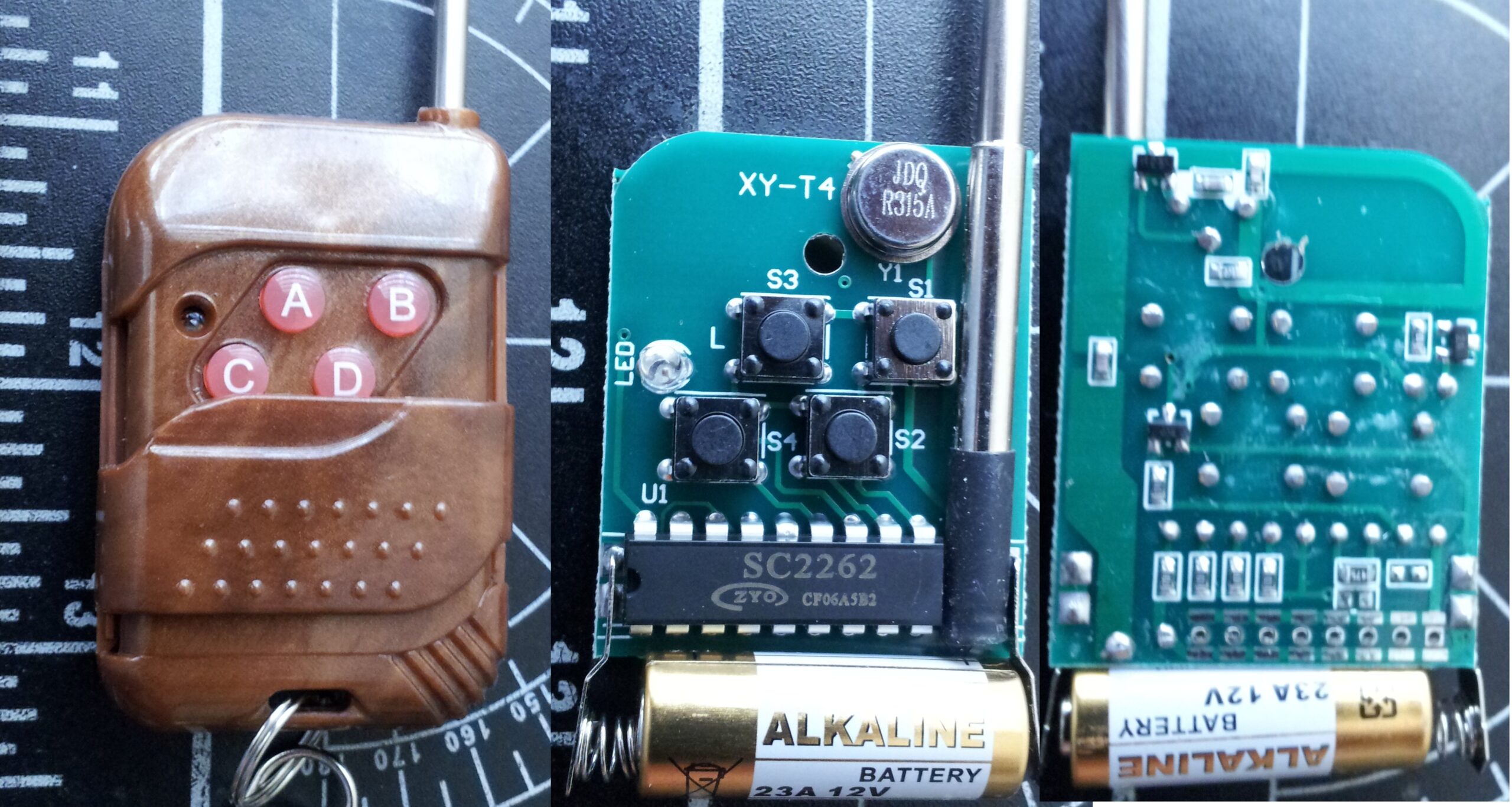
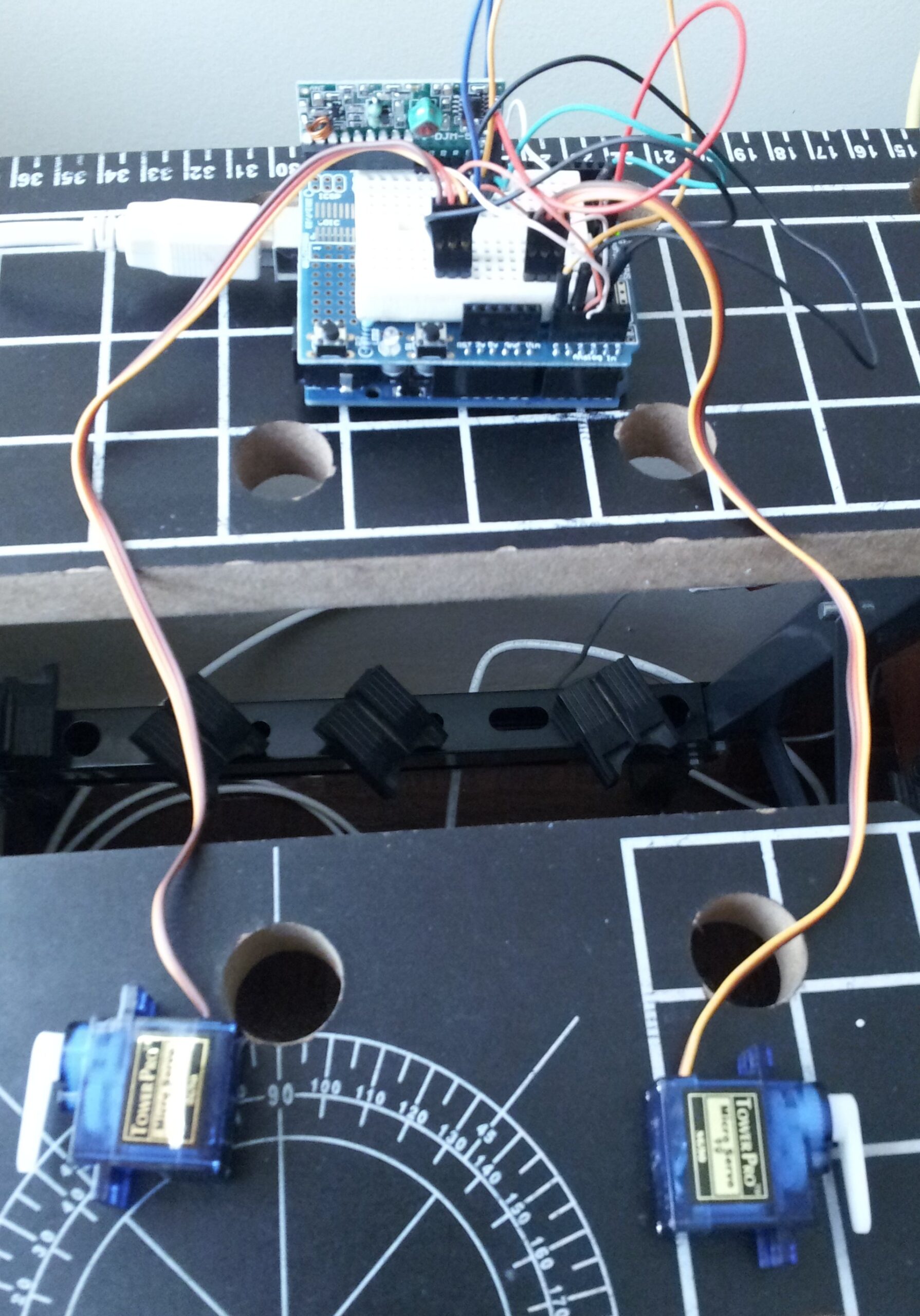
In this little example an Arduino UNO board with 2 micro servo motors will be controlled remotely using an XY-DJM-5V SC2272-M4 RF controller. Note that this module is intended for be used as a simple relay on its digital pins, other modules allow more deep radio frequency communication.
Other RF module example: Arduino with RF module, custom data transmission.
Download PT2272-M4-S18 datasheet from Princeton Technology Corporation.
Setting up the radio frequency:
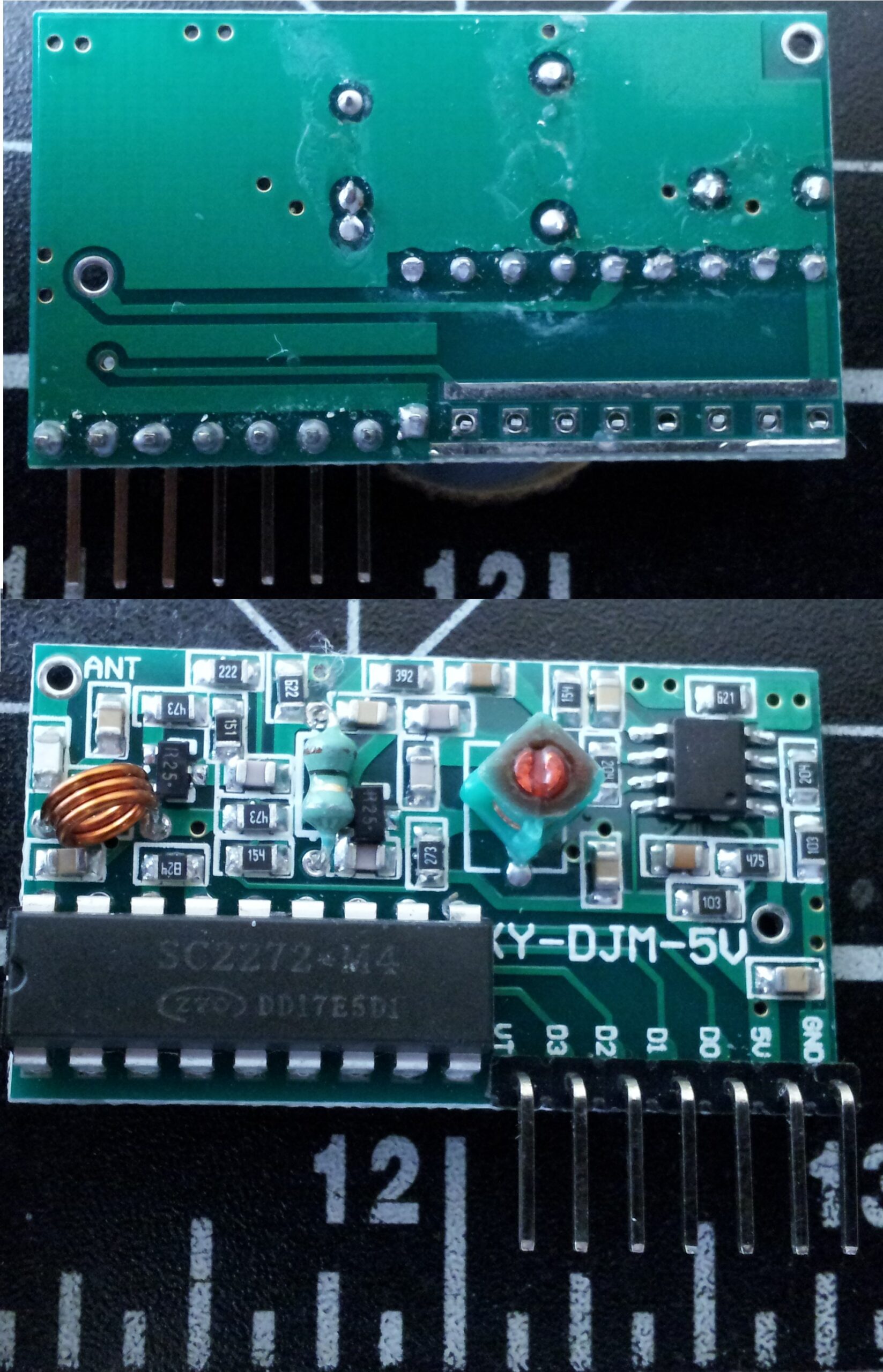
To correctly use the RF module in any aplication the user must make sure to be working on the right frecuency, this means that the emitter and receiver are tunned on the same “adress” to comunicate, the XY-DJM-5V module with its SC2272-M4 chip allows the user to set the ideal frecuency to pair any set of instruments. This is done by soldering the free row of pins on the chip to the strips on top or bottom of the row, the combination of this soldering will give an “unique” scheme that will be used to transmit the signal, repeating this procedure on the controller, will pair the two of them on right frecuency, notice that making the same conection on multiple controllers or recievers will create a usefull arrangement.
For this example the pins were not soldered, so both, the controller and receiver are in a standar configuration, this may be not recomended since any brand new controller can interfere with the servos.
Installation:
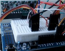
- The XY-DJM-5V module has 7 pins, the first two GND and 5V will be connected to ground and power pins on the Arduino board.
- The D0,D1,D2,D3 pins respond to a digital output from the toggle of the buttons on the remote controll, when a button is pressed the pin goes from GND to HIGH, conecting each one on this to the analog ports of the Arduino board will give the needed feedback.
- The servo motors, in this case, will be connected to the GND and 5V alimentation or the board, the control lines (yellow) will receive signals from the 9 and 10 digital pins.
Servo motors on Arduino: Be advised, the power regulation on Arduino boards (and any other micro controller based device) is not designed to carry on over the energy needed to move multiple or even a single little servo motor, this doesn’t means that the configuration wont work like in this example, but it could drain enough power to disturb the control from the micro controller. An aditional supply circuit its required to power any motor or actuator controlled with arduino; for the simplicity of this example this circuit is obviated.
Arduino Code:
Servo myservo;
Servo myservo2;
int estado1 = 0;
int estado2 = 0;
int pos1 = 0;
int pos2 = 0;
void setup() {
myservo.attach(9);
myservo2.attach(10);
Serial.begin(9600);
}
void loop() {
if(analogRead(0) > 100) estado1 = estado1 + 10;
if(analogRead(1) > 100) estado1 = estado1 – 10;
if(analogRead(2) > 100) estado2 = estado2 + 10;
if(analogRead(3) > 100) estado2 = estado2 – 10;
if(estado1 == 110) estado1 = 100;
if(estado1 == -10) estado1 = 0;
if(estado2 == 110) estado2 = 100;
if(estado2 == -10) estado2 = 0;
pos1 = map(estado1, 0, 100, 720, 3000);
pos2 = map(estado2, 0, 100, 720, 3000);
myservo.writeMicroseconds(pos1);
myservo2.writeMicroseconds(pos2);
Serial.print(pos1);
Serial.println(pos2);
delay(100);
}